It is assumed that you have already skinned the weapon mesh properly and imported it as an Unreal Engine skeletal mesh.
The normal convention is to use the prefix SK_xxx for skeletal meshes.
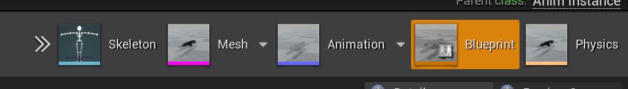
You will be familiar with the Unreal Engine 4 feature that when you open a skeletal mesh or its associated animation blueprint (ABP_xxx) or physics definition (PHYS_xxx), a special viewer will open with a set of buttons allowing easy switching between skeleton, skeletal mesh, animation, animation blueprint and physics:
Figure 1. Editor files for M16A4 in-game item (not including master blueprint, wwise sounds, and so on)
¶ Skeleton view
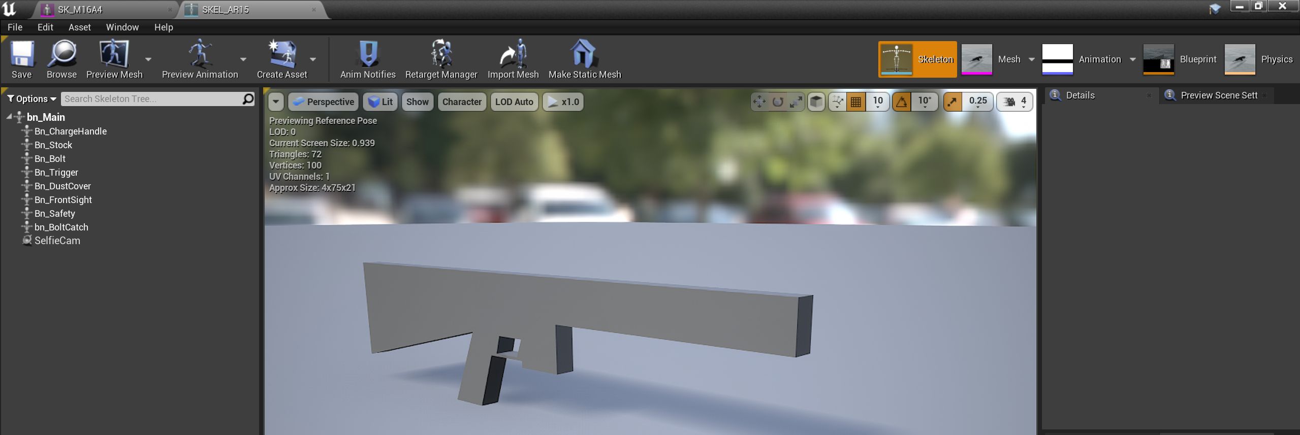
Figure 2. weapon_mk16_skel.jpg
This view allows you to visualise the weapon bones (discussed in the skinning link above). You will be (re)using an existing skeleton from GBCore, so the ability to add skeletal sockets will not be needed.
| In some cases, external editors may add extra bones to the skeleton when importing from Unreal Engine 4. In particular, some programs may add a set of 'end' bones, as in the following diagram. These excess bones need to be removed, or else they will cause errors or crashes when your mod is used. |
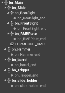
Figure 3. Skeleton view showing a set of end bones that have been added by an external program
¶ Skeletal mesh view (SK_xxx)
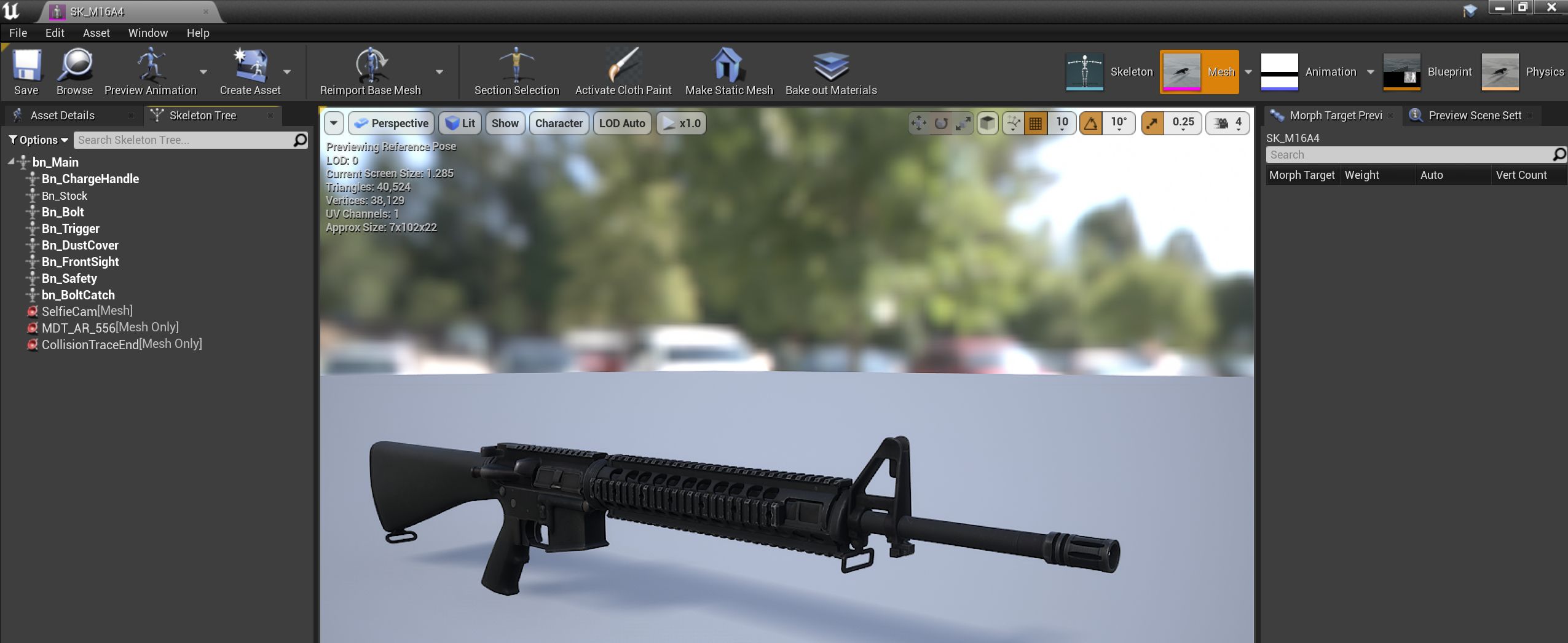
Figure 4. weapon_m16_skmesh.jpg
This view allows you to preview the mesh that you have imported and to add mesh sockets (as opposed to skeletal sockets) to define custom attachment points or similar for your weapon.
There are some sockets that you need to add:
-
SelfieCamThe viewpoint for the 'selfie cam' spectator view. The selfie camera points from this socket towards the operator eyes. Every weapon mesh should have one of these. -
<SuppressorSocketName>A socket name to define where a suppressor attaches, if applicable (not all weapons take suppressors). This socket name needs to be filled in also in the Muzzle Device Thread field in the GBBarrel component of a weapon. The same socket name is used to determine which suppressors (if any) are compatible with a particular barrel (and thus weapon). For a list of in-game suppressor types and associated socket names, see GROUND BRANCH suppressors. -
CollisionTraceEndFor the purpose of collision checking, it is assumed that the end of the barrel component is at the end of the mesh. If not, such as on the M16, you will need to manually create a CollisionTraceEnd socket to define the very end of the weapon/barrel.
Other socket names may exist to denote a particular function for a particular part of the skeletal mesh. For example:
-
SIDEMOUNT_AKTo indicate a placement for a rail adaptor (used on some old AKs) -
TOPMOUNT_RMRTo indicate a placement for an RMR plate (on sidearms/pistols)
¶ Animation view (ABP_xxx)
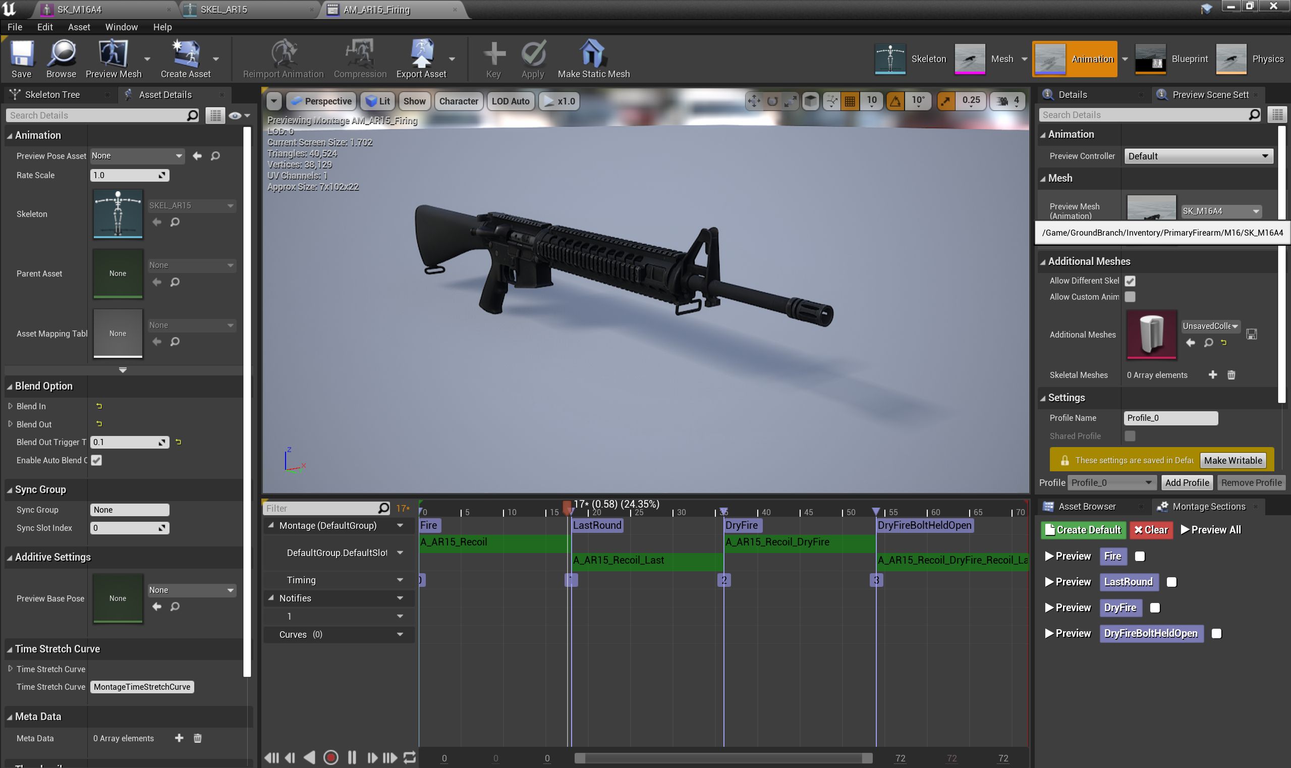
Figure 5. weapon_mk16_animation.jpg
This view lets you preview assigned animations/montages for particular operations on/with your weapon, if you put your new weapon mesh into the Preview Mesh field at the top right. Your weapon should animate in this screen in the same was as it will in-game in response to the selected operations/animations.
¶ Animation blueprint view (ABP_xxx)
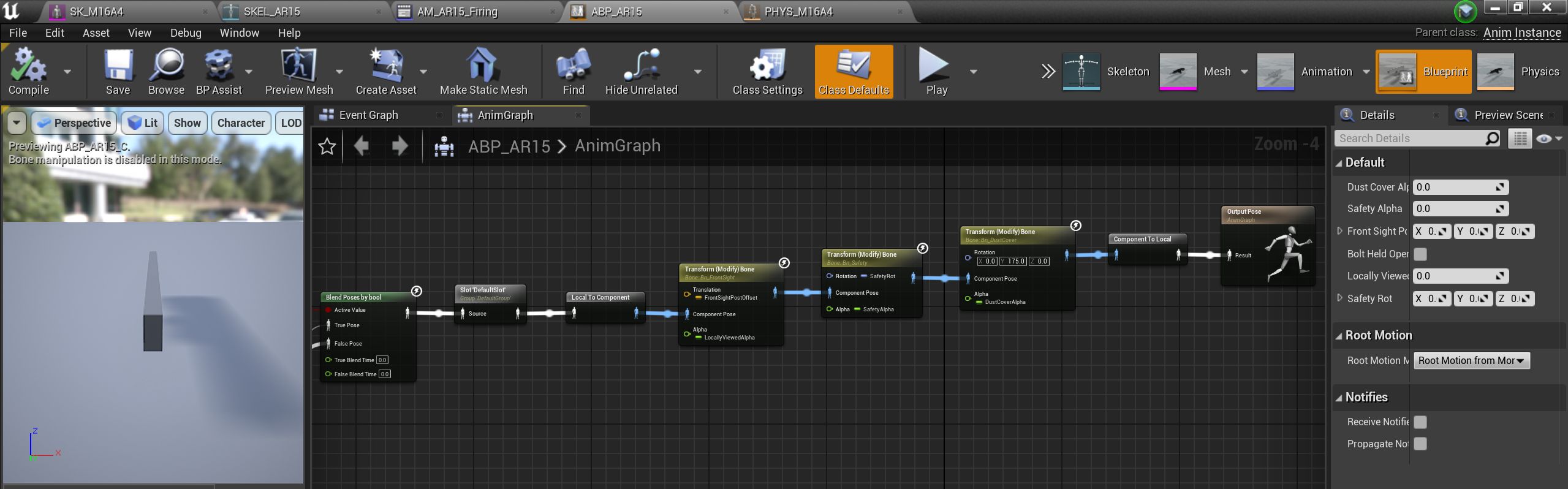
Figure 6. weapon_m16_blueprint.jpg
This view lets you alter the internals of the animation blueprint, to provide custom poses and other custom animation features. The animation blueprint is a separate entity to the weapon blueprint, and it is really for advanced use only. If you don’t know what you are doing, leave this well alone, is our suggestion.
¶ Physics view (PHYS_xxx)
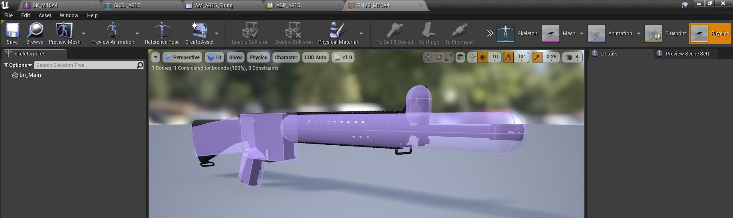
Figure 7. weapon_mk16_physics.jpg
This view allows you to define a simplified physics representation of the weapon, principally used for (but not limited to) defining collision for the weapon. Physics collisions are comprised of simple (as simple as possible, in fact) primitive shapes such as capsules, boxes and spheres.
| All sight rails (that is, rails to which sights can be attached) must be 'poking out' of the physics collision elements. If they are within the physics elements, it will not be possible to attach any sights. See the top rail in the picture above. |
| Make sure your component rails are attached in the correct orientation (origin/pivot point at rear of weapon) or you may have a problem that looks like incorrect physics element placement, but isn’t. |
¶ LODs (Level of Detail)
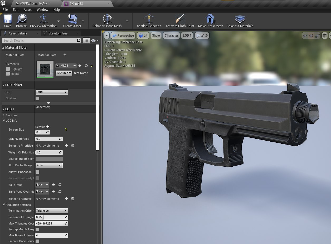
Figure 8. Editing Level of Detail 1 (LOD 1) for the Mk23 mod example
One important step in preparing a skeletal mesh is to set up Levels of Detail (LODs). In the example above, LOD 1 for the Mk23 handgun is being edited, with the LOD appearing at screen size 0.3 and below. In this case, LOD 1 uses 0.25 (or 25%) of the total number of polygons used in the base LOD (LOD 0). This means that as the mesh moves further from the player, successively fewer polygons are used to render it. Here you can see flaws in the model caused by the reduction in polygons (on the barrel, for example), but when the model is only at 0.3x screesize, the flaws are unnoticeable.
This is a standard and well-known feature of Unreal Engine 4, and other engines, so no more will be said about it, but please do remember to set up LODs for all of your in-game items.
| If you have a particularly high poly model, as can sometimes happen for marketplace purchases and the like, you may need to apply a reduction even to the base model (LOD 0), though it may be more convenient or appropriate to do this before importing the model into the engine. |
¶ See also
Using the GROUND BRANCH skin system to create different versions of your model without needing to make multiple skeletal meshes.
| The GROUND BRANCH skin system is not currently supported in relation to weapons. This may change in later versions of GROUND BRANCH. |